How to improve production efficiency with a PV EVA gasket die cutting machine?
To improve production efficiency with a PV EVA gasket die cutting machine, measure first-pass accepted gaskets per scheduled production hour, identify the biggest recurring loss, and test one change at a time. Start with feed stability, clean part and waste release, and repeatable die changes. Increase speed in steps after the cut dimensions and edge quality are stable. If parts pile up at the discharge or the machine stops for short jams, improve that operation first. Validate gains through a run that includes a roll change, a restart and normal inspection and collection. Track EVA consumption alongside output so a faster line does not hide more material waste.
Measure the losses before changing the machine speed
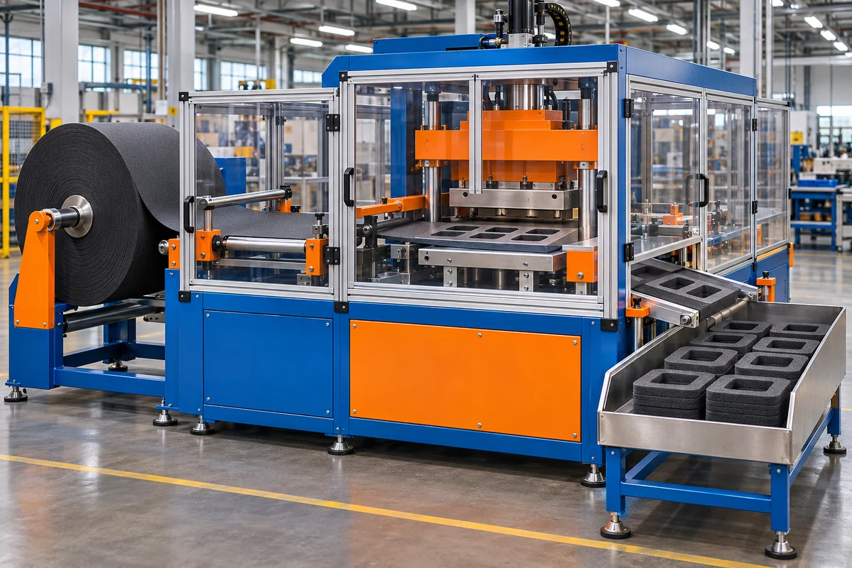
Use the machine counter to collect data and the quality count to decide whether the change helped. If the machine counts strokes, multiply by the active cavities only to estimate gross output. Count rejected, incomplete and missing pieces so the accepted total reflects what actually reaches the specified delivery format. If your customer needs liner-backed reels, define a qualified reel as part of the acceptance criteria. Loose cut parts and finished reels represent different production stages.
Set a measurement window that includes normal production losses. For example, schedule a two-hour trial and count planned in-window roll changes, changeovers, short jams and first-piece checks against those two hours. Define any exclusions before the test and apply them to both runs. Record the gasket drawing revision, EVA construction and lot, thickness, web width, die, cavity count, operator staffing and machine settings. A different roll width or more downstream staffing can change the result even when the machine settings stay the same. If you already track overall equipment effectiveness (OEE), its availability, performance and quality factors help separate stop time, slow running and lost pieces.[1]
| Signal on the line | What to record | First investigation |
|---|---|---|
| Parts vary in length or hole position after a roll change | Part dimensions before and after the change, roll identification and guide settings | Reproducibility of threading, guides and feed setting |
| Repeated short stops at the die | Stop code, time, location and photos of rejected parts where safe | Part release, waste buildup or incomplete cutting |
| Machine cycles faster but discharge fills up | Accepted count, queue size and collection stops | Collection or inspection capacity |
| Frequent startup rejects | Scrap length or mass, die revision and time to first approved piece | Setup sequence and first-piece release |
| Good parts fall during the shift | Reject type by time, lot and cavity | Tool wear, material variation or recurring feed drift |
Stabilise EVA feeding and remove waste consistently
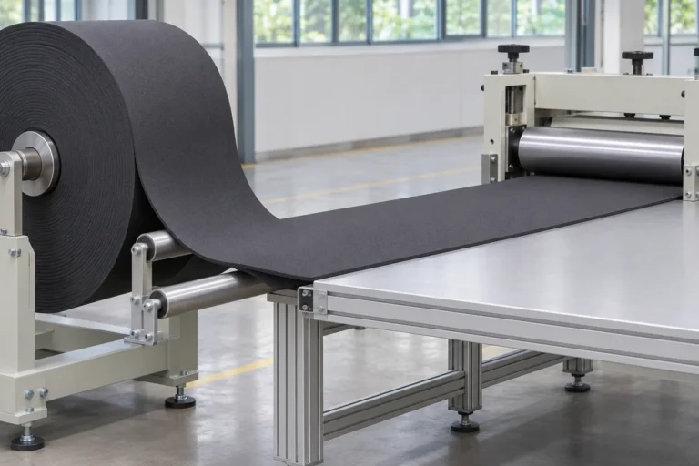
Start at the unwind and follow the stock to the finished collection point. Confirm the roll can be supported by the proposed unwind throughout its usable diameter. Record how the web enters the guides and how the feed behaves as the roll becomes lighter. If the material is soft or tacky, inspect for slip, marking and stretching before increasing roller pressure. Use the machine supplier’s adjustment procedure and verify the result with your material. Roll size, a liner and the way the web is driven can all affect the setup. Web-converting tension controls may compensate for changes in roll diameter, depending on the equipment and application.[2]
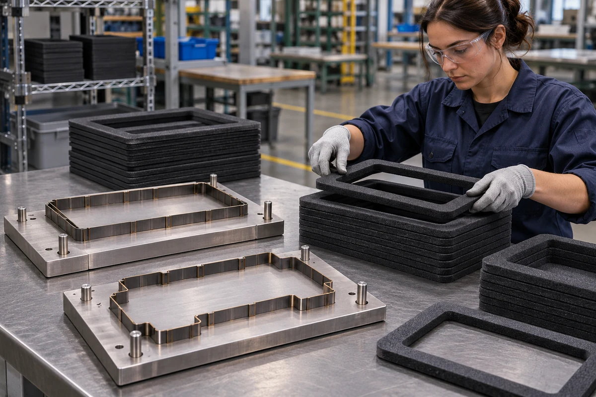
Then follow the waste. A through-cut ring creates an internal slug and an outer skeleton. A rectangular strip with small holes may create several tiny slugs at every cycle. Write down where each waste stream should go. If a part or slug comes back with the die or blocks the chute, trace what happens during the stop-and-restart sequence. For an adhesive-backed gasket supplied on a liner, test whether the cut depth, liner integrity and waste stripping stay reliable as the run continues. Controlled-depth cutting can leave the part attached to its liner for downstream handling.[3]
Review the die layout with the tooling supplier. More cavities or a staggered layout may improve output or EVA utilisation if the web can feed, cut and release consistently. Leave enough material between cutouts and at the edges for the proposed waste path. Approve the layout using cut samples and accepted count across all cavities. Compare material consumption per thousand first-pass accepted parts, including startup scrap, the remaining skeleton and rejected gaskets. Use either kilograms or square metres per thousand and keep the measurement consistent across trials.
| Material or output format | Improvement to test | Release criterion |
|---|---|---|
| Thin, flexible EVA roll with punched holes and straight ends | A repeatable unwind, alignment and indexing setup | Hole-to-edge and cut-length tolerances hold across a roll change |
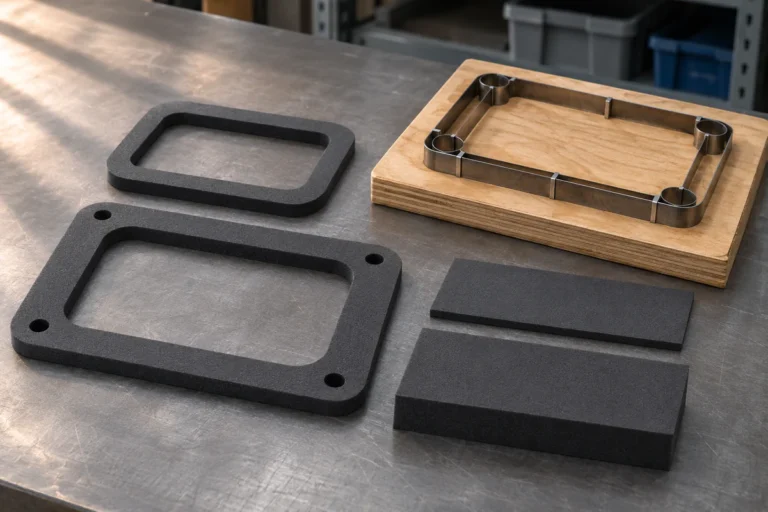
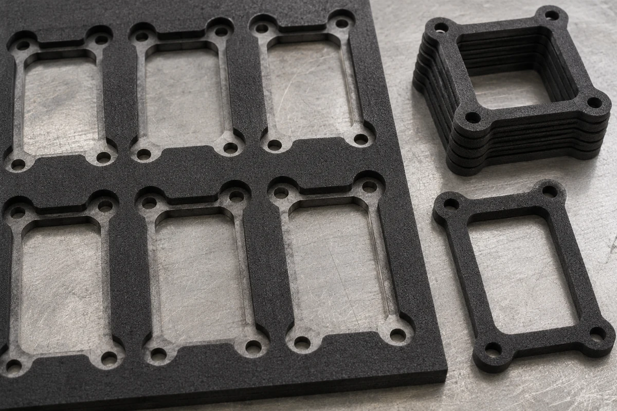
| Foam frame with a centre opening | Die layout, slug release and scrap path | All cavities release complete, undamaged frames throughout the trial |
| Liner-backed adhesive gasket | Controlled cutting depth and waste removal | Liner meets the agreed inspection and the matrix strips consistently |
| Loose parts packed in batches | Collection bin, tray or transfer matched to inspection and packing | No recurring backup during the measured production window |
Shorten roll and die changes safely
Define changeover time as the interval between the last accepted piece of the old job and the first approved piece of the next job at the agreed production settings. Break the interval into material staging, tooling setup, threading, recipe setup, first-piece inspection and release. Record waiting time separately. A missing die, an unclear drawing revision or an unavailable inspector can add time even if the actual tool change is quick. Include setup scrap, since a changeover can be fast on the clock and still consume a long strip of EVA.
Use the setup reduction principle of preparing suitable tasks before the machine stops. Stage the identified die, the next roll, the current drawing, the approved sample and inspection tools in a designated area. Record validated machine settings by material and part revision, using recipe storage where available or a controlled setup sheet. Group compatible orders by tool or feed setup when product mix, delivery commitments and lot traceability allow. The method of separating preparatory work from tasks that require a stop comes from single-minute exchange of die (SMED).[4]
Keep die removal, cleaning and other work inside a hazardous area within the equipment’s safe procedures. For servicing covered by U.S. OSHA hazardous-energy rules, follow the facility’s applicable energy-control procedure.[5] Once the next job starts, use a first-piece check for the dimensions and appearance most likely to move during setup. Track the time and scrap needed to pass that check rather than rewarding a restart that releases unapproved pieces. If the largest delay is first-piece approval, look at gauge readiness, sample transport and the approval handoff before investing in faster tool mounting.
Validate the gains over a representative run
Use a baseline and a trial with the same job, tooling and quality criteria whenever practical. Log the reason and duration of each stop. Increase the machine speed in controlled steps within the approved operating range. At each step, check the dimensions that depend on feeding and registration, then inspect for partial cuts, compressed edges or damaged liners as applicable. Observe whether the waste path or finished collection becomes the limiting step. Once a setting meets the quality criteria, test it over an agreed production window with the normal staffing and handling.
| Two-hour example | Baseline | Trial |
|---|---|---|
| Scheduled production time | 120 min | 120 min |
| In-window stopped time | 30 min | 18 min |
| Gross pieces produced | 10,000 | 10,800 |
| Rejected pieces | 600 | 300 |
| First-pass accepted pieces | 9,400 | 10,500 |
| First-pass accepted pieces per scheduled hour | 4,700 | 5,250 |
The illustrative trial improved first-pass accepted output by 11.7%, calculated as the increase of 550 pieces per scheduled hour divided by the baseline of 4,700. Repeat the comparison before setting a production target. The example is a calculation method. Actual improvements depend on the work mix, stock, tooling and cause of lost time. For a purchase or upgrade, agree on a sustained-output target and a test protocol with your supplier. Specify the material, die, run duration, quality sampling, interruption accounting and collection method. Ask for a record of accepted pieces and scrap, along with samples from the beginning, middle and end. Capture any additional labour or tooling costs. The resulting cost per thousand accepted parts can help compare upgrades such as a powered unwind, revised tooling or a different collection arrangement.
Insights: How HAOXINHE evaluates EVA gasket throughput
The CUTOPIX HX-200DK-B2 combines automatic roll feeding, positioning, punching and cutting for small thin, flexible gasket parts. We review the stock and tooling together to determine whether the feed, cut pattern and collection method fit the application. Throughput on your part depends on the gasket geometry, material and die configuration. A sample run gives your team a basis for confirming the cut quality and discussing a representative production trial.[6]
Send the material type, thickness, width and roll details, a drawing with tolerances, the desired accepted output and how you need the parts delivered. Specify whether you need holes, a shaped outer perimeter, a centre cutout or a liner-backed reel. If your existing process loses time, include a short video or a shift log showing where it stops and how often. Include drawings for any connected unwind, scrap rewind or downstream equipment. See the CUTOPIX cutting machine range or use the CUTOPIX inquiry form or email cherryhaoxinhesz@gmail.com to discuss a sample test.
Frequently asked questions
Does a multi-cavity die always increase production efficiency?
Extra cavities can raise parts per stroke when the tool load, feed, ejection and collection can handle the layout. Count accepted parts from each cavity. A recurring defect in one cavity can increase material use and sorting time even when gross production rises.
When should we consider an automatic scrap rewinder?
Evaluate it if waste handling repeatedly stops the machine on jobs with a continuous waste web. Test waste strip strength, reel formation and the effect of rewind tension on the cutting operation. Loose slugs or a fragile skeleton may need a different removal method.
How often should we replace or service the die?
Follow the tooling supplier’s instructions and track condition alongside rejects and intervention time. Record which cavities show incomplete cuts or release issues, and compare results across material lots. This helps distinguish recurring tooling wear from a change in feed or stock.
Where should a production team start?
Track one representative job using accepted gaskets, scheduled hours, stops and EVA consumed. Trial one change against the largest recurring loss, then confirm the gain through normal roll handling, inspection and collection. Use the verified setup for repeat jobs and bring the same measurements to a supplier if the line needs a tooling or equipment change.
References
- Lean Enterprise Institute — Overall Equipment Effectiveness. Source
- Maxcess — MAGPOWR Cygnus Digital Tension Readout and Control Instruction Manual, section 8.2. Source
- Preco — Rotary and Flat Bed Die Cutting. Source
- Lean Enterprise Institute — Single Minute Exchange of Die. Source
- OSHA — 29 CFR 1910.147, The Control of Hazardous Energy. Source
- CUTOPIX — Solar PV EVA Gasket Punching & Cutting Machine HX-200DK-B2. Source