How to maintain a PV EVA gasket die cutting machine for long-term performance?
Maintain a PV EVA gasket die cutting machine by keeping the feed path clean, inspecting tooling and cutting surfaces for wear, and checking finished parts against an approved sample after each setup or service. Build preventive maintenance around the manual for your machine and its installed options. Record recurring defects, tooling changes and accepted output so you can catch deterioration early. When servicing exposes workers to hazardous motion or stored energy, have authorized personnel follow the site’s machine-specific isolation procedure and verify isolation before work begins.[1] A useful daily habit is to compare the first good gasket with the last good one from the previous run and record any change.
Build a preventive maintenance schedule around your machine
Start with the machine serial number, manual revision, installed feed and waste-handling options, tooling list and approved service supplies. Keep the manual and tooling instructions at the line where operators and technicians can find them. If a machine has been retrofitted with an unwind or a different die holder, add its instructions to the same record. A team working from the original installation drawing alone may miss components added after commissioning.
The checkpoints below are a planning template. Assign the actual cleaning, lubrication, inspection and replacement intervals from the manufacturer’s instructions. Where the manufacturer permits, adapt inspection frequency to the production history. A line running adhesive-backed foam for two shifts may accumulate residue at a different rate from a line that runs unbacked strips for short batches. Record observations before deciding whether to shorten an interval.
| Checkpoint | What to verify | What to record |
|---|---|---|
| Before a production run | Approved tooling and recipe, correct stock, visible condition of guards and a clear external collection area | Job, die revision, material lot and operator |
| After a roll, material or die change | Web position, part dimensions, cut completion and release-liner condition where relevant | First-piece decision and any approved setup changes |
| At the scheduled cleaning stop | Foam debris or adhesive residue on approved cleaning points and scrap buildup around collection equipment | Location and amount of buildup, recurring jams and follow-up |
| At the manufacturer’s service interval | Specified wear points, approved lubrication, drive condition and required safeguard checks | Service performed, parts replaced and next due date |
| After repair or an unexplained stop | Cause, applicable restart checks and results of a controlled trial | Alarm details, service action and release approval |
Keep operator checks accessible from the normal work position. Assign work inside guarded areas, electrical cabinets or hazardous zones to qualified or authorized personnel under the applicable procedure. In the United States, OSHA addresses hazardous energy control during covered servicing and guarding of hazards such as points of operation and in-running nip points.[1][2] Your site should use the requirements applicable to its location and equipment.
Inspect the die and its mating surface as a pair
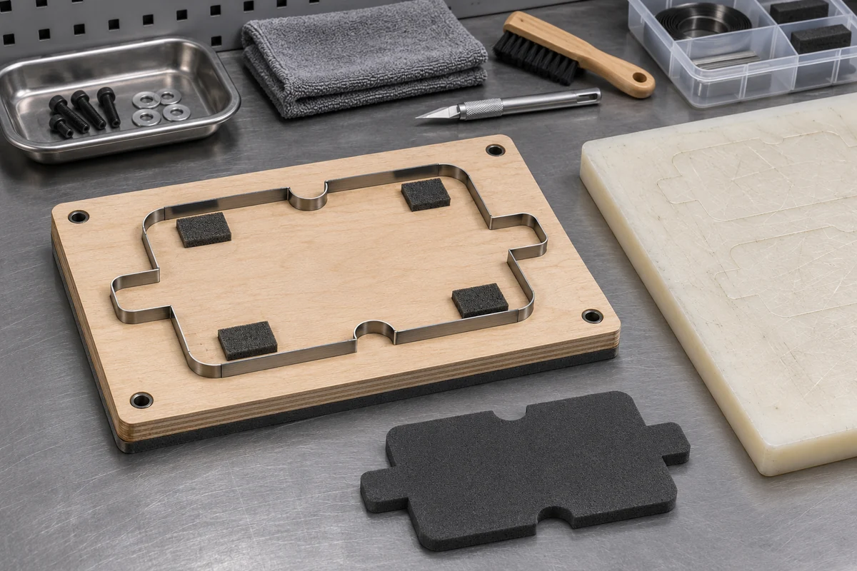
Concept illustration of removable tooling and a cutting surface on an inspection bench.
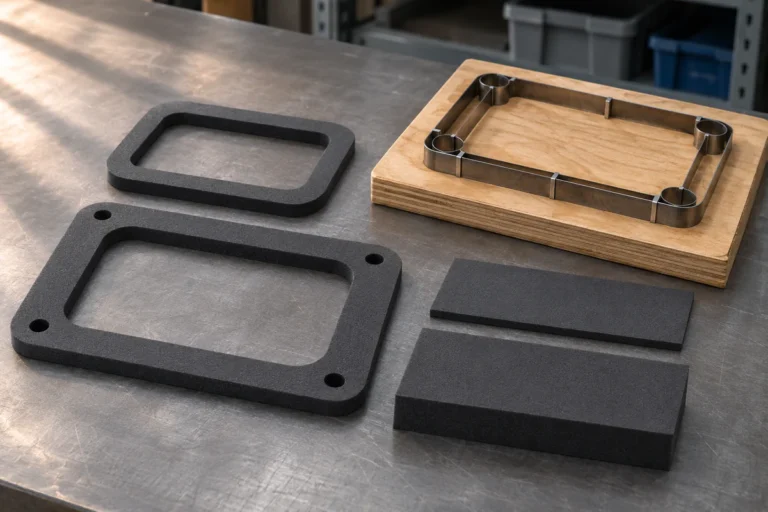
A cut defect that repeats in the same corner of every gasket is a useful clue. Mark the corner on a rejected sample and note which cavity produced it. Once the machine is in the approved service condition, have the technician inspect the corresponding part of the die and its mating surface. Depending on the tooling design, that surface may be a cutting pad, anvil or another specified component. Look for wear, damage, contamination and seating problems according to the tooling and machine instructions. If the problem is isolated to one cavity, compare its output with the other cavities before changing settings for the entire tool.
A cut profile that looks pinched in the middle of its thickness may also come from foam compression during cutting or an unsuitable cutting-rule profile. National Steel Rule discusses how rule geometry can affect the wall shape when die cutting thicker foams.[3] Send the die maker a close-up of the edge and a material sample if a new grade produces this defect from the first run. That evidence helps determine whether the root cause is tool design, stock behavior or equipment condition.
Store removed dies in protective holders identified by part number and revision. Keep a record of when each die enters service, which cavities show wear and what the last accepted parts looked like. Follow the toolmaker’s instructions for cleaning and storage. Refer damaged or dull edges to the qualified tooling provider, and plan a production-sample check when a refurbished die returns. Some cutting surfaces can be reused or repositioned by design. Other designs prescribe replacement, so follow the instructions for the installed component.
Keep the feeder, guides and scrap path clean
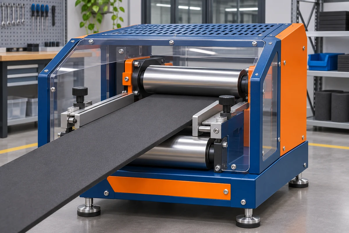
Concept illustration of the feed path and edge guides on a roll-fed unit.
Look at where the defect first appears. If part length varies but the contour stays sharp, review feeding and stock handling before changing the die. If holes move relative to the outer cut, compare where the stock enters the tool and whether the movement starts after an unwind, splice or roll change. Where normal guarded observation is possible, note whether the web stays centered or moves from side to side. Record whether the fault occurs near the beginning or end of a roll. A record of when the problem starts is usually more helpful to a technician than a photo of a single rejected part.
Use only the cleaning materials and methods specified for the installed rollers, sensors and guide surfaces. Adhesive-backed stock can leave residue where the backing or exposed adhesive contacts the feed path. Even a small buildup can change how the web travels, so document the location before cleaning. Check a sample afterward to see whether feed repeatability improves. Arrange qualified inspection of worn rollers, damaged guides or recurring sensor faults under the machine’s service procedure.
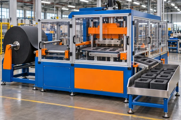
Pay attention to discharge as well. A trim web can tug on a thin frame if parts are still attached at a corner or if the waste path changes as the take-up roll builds. Look for bridging between the gasket and its surrounding trim, a jam in the collection area, or sudden changes in waste-roll shape. Confirm the waste configuration and separation method for the actual material. For lines combining punching with a separate cross-cut step, check hole-to-edge position and cut length independently. The CUTOPIX Solar PV and New Energy equipment pages show why feed and collection details vary by process.
Verify cut quality after every change that affects the process
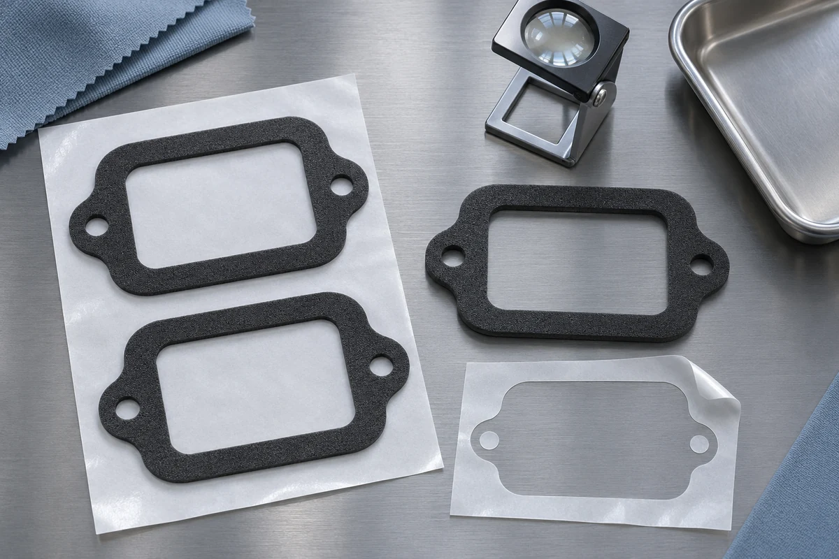
Concept illustration of release-liner inspection and a peeled gasket sample.
Keep an approved gasket sample, the current drawing and the inspection method together. Compare the first pieces after a tool change, material change or service with that baseline. On compressible stock, use the same agreed measuring method each time and identify when the measurement was taken. The procedure should define which dimensions matter, which cavities to sample and how to check the internal opening. A different measurement force or inspection method can make two otherwise similar samples appear different.
A through-cut part should release as required by the application without leaving unacceptable attached corners or internal slugs. On jobs that specify kiss-cutting, assess both the way the gasket peels and the condition of the retained liner. Evaluate parts from each active cavity when using multi-cavity tooling. Also check samples from a representative run under usual production conditions to catch problems that only appear after a roll has been running for a while. A short first-piece check is useful for releasing setup, while a longer sample series helps reveal material feed drift.
| Symptom | First comparison | Useful evidence for maintenance |
|---|---|---|
| Attached corner repeats in one position | Same cavity and corner across multiple samples | Annotated defect photo, die ID and matching cutting surface condition |
| Part length varies across the roll | Feed position and stock behavior near the first fault | Roll stage, material lot, consecutive measurements and recorded alarms |
| Liner tears after peeling | Current laminate and approved setup versus the last accepted run | Peeled gasket, retained liner and backing specification |
| Frame distorts at collection | Part shape before and after waste separation where safely observable | Finished sample, scrap shape and approved observation of the discharge |
| Defect starts after a tooling change | Revision, material stack and first-piece release record | Last good sample, first rejected sample and changeover notes |
Keep samples and label consecutive pieces when the fault is intermittent. Compare one approved change at a time where practical and record the result. This makes it easier to tell whether a correction actually resolves the defect over the run.
Use downtime and spare-parts records to guide service
Set up one maintenance log that follows each gasket job from setup to release. A useful entry identifies the machine, tooling revision, stock lot, time in production, the exact symptom and the action taken. Track accepted output and unplanned stoppages by cause if operators can do it consistently. A rising number of resets means something different if every event follows a liner change than if faults occur across all material grades. Separate scheduled cleaning time from jam recovery so you can see where the hours go.
| Record to keep | How the record helps |
|---|---|
| Machine serial number and installed options | Identifies the service documentation and compatible parts |
| Die revision, cavity and first-piece result | Helps isolate defects tied to a specific tool or cavity |
| Wear parts changed and dates or cycle counts | Shows which replacements recur and when to reorder |
| Alarm text, stop time and part samples | Gives technicians evidence about the operating conditions at failure |
| Approved recipe backups and service notes | Supports repeatable setup and traceable recovery after authorized work |
Identify the wear items that can stop your line. Depending on your configuration, these may include the specified cutting surface, a tool for your highest-volume part, feeder wear components or an approved sensor replacement. Confirm compatibility by machine serial number and component reference. Ask the supplier for lead times and group consumables by the jobs that depend on them. Where the controls support recipe or parameter export, follow the supplier’s documented backup and restore procedure and restrict access to authorized personnel. After service, complete the required restart checks and release production only after the agreed part inspection passes.
Frequently asked questions
How often should I lubricate the machine?
Use the service schedule for your machine and each installed option. Confirm the designated lubrication points, lubricant grade and quantity with the manufacturer. The schedule and lubrication requirements can vary across assemblies.
Should I increase cutting pressure when EVA foam stops cutting cleanly?
Start by comparing the defect location, tooling condition, material lot and approved settings. A pressure increase can mask a local issue and may damage the liner or accelerate wear. Have qualified personnel use adjustments authorized by the manufacturer for the specific tool and material.
Does the same maintenance plan apply to EVA encapsulation film?
Identify the stock and conversion process first. This guide covers mechanical conversion of EVA foam gaskets and similar laminates. PV encapsulation film and edge seals serve different functions in a module and may be processed on different equipment. NREL discusses encapsulants and edge sealants as distinct module materials.[4]
Insights: How HAOXINHE supports EVA gasket equipment
The CUTOPIX HX-200DK-B2 is an automatic cold punching and cutting machine for thin EVA gaskets and other flexible materials. CUTOPIX offers material testing, configuration review and remote technical support. Maintenance documentation and replacement parts should be matched to the serial number, installed tooling and any optional modules. When evaluating a new project, ask for the service documentation and agree on which material, dimensions and visual criteria will be used to accept the cut samples.
For an existing machine, send the serial number, an alarm screenshot if available, the material grade and thickness, the finished drawing, and photos of a good part and a rejected part. Note when the issue started and any recent stock, tooling or setup change. For a new application, include stock width and format, target output, and photos or drawings of the gasket and layer construction. Contact CUTOPIX or email cherryhaoxinhesz@gmail.com for a configuration or service review.
References
- U.S. Occupational Safety and Health Administration — 29 CFR 1910.147, The Control of Hazardous Energy. Source
- U.S. Occupational Safety and Health Administration — 29 CFR 1910.212, General Requirements for All Machines. Source
- National Steel Rule — Specialty Rules Solve Diecutting Problems. Source
- National Renewable Energy Laboratory — F. J. John Pern, PV Module Encapsulation: Materials, Process, and Reliability. Source