What is the difference between hydraulic and pneumatic PV EVA gasket die cutting machines?
A hydraulic PV EVA gasket die cutting machine uses pressurized hydraulic fluid to drive the cutting stroke. A pneumatic machine uses compressed air. Hydraulic drives are often worth evaluating for high-force jobs such as wide frame gaskets or multiple cavities that cut at once. Pneumatic drives are often candidates for smaller, short-stroke cuts when a stable air supply can deliver the required force and flow. The better choice is the one that produces acceptable gaskets at the required rate on your actual material. Compare the working force at the die, usable cutting area, finished-part quality and utility demand under production conditions.[1][2]
How hydraulic and pneumatic gasket die cutters compare
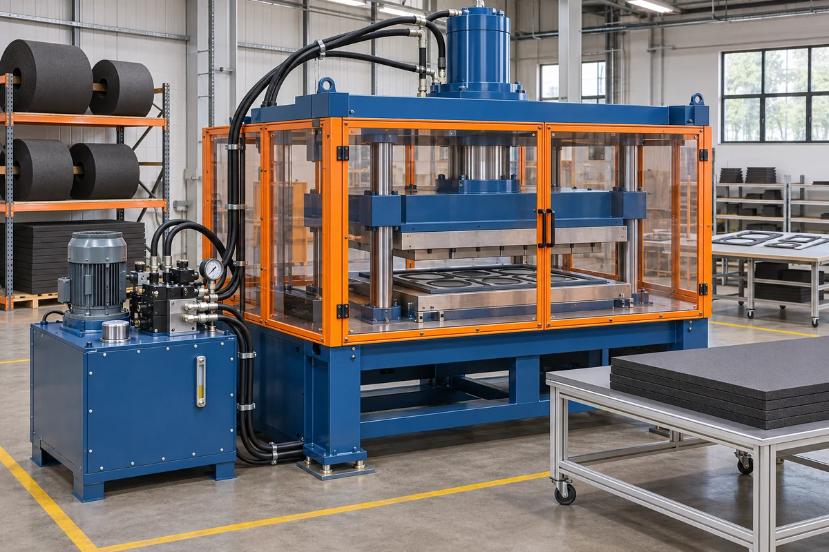
Concept illustration of a hydraulic flatbed press and its power unit.
In a typical hydraulic setup, a pump moves fluid from a reservoir and valves control the cylinder. The system develops force as the tooling meets resistance, within the rated limits of the press and circuit. Hydraulic fluid is much less compressible than air, and industrial hydraulic systems can deliver substantial force from a compact cylinder. The supplier still needs to establish how much of that force the frame, platen and tool can apply over the proposed working area. A press rated for a central load may have separate limits for loads shifted toward an edge.
A direct pneumatic setup uses a valve to send compressed air to a cylinder. Its working force depends on the effective piston area and the pressure actually available during the stroke. With high cycling demand or a restrictive supply path, pressure at the machine can dip even if a static gauge reading looks fine. Ask the supplier to state the minimum pressure and air consumption at the required cadence. If a machine uses compressed air to feed or eject parts, confirm separately what drives the cutting stroke.
| Comparison | Hydraulic drive | Direct pneumatic drive |
|---|---|---|
| Working medium | Pressurized hydraulic fluid | Compressed air |
| Jobs to evaluate first | Long cutting perimeters, larger tooling footprints and higher combined cutting loads | Smaller profiles, shorter strokes and cutting loads that fit the available cylinder and air supply |
| Main utility question | What electrical service and thermal capacity does the power unit require? | What inlet pressure, airflow and air quality are needed during the run? |
| What can limit cadence? | Pump flow, stroke profile, return motion or downstream handling | Valve and line flow, exhaust, supply pressure recovery or downstream handling |
| Maintenance to budget | Hydraulic fluid and filter service, seals, hoses and leak checks as specified | Air treatment, tubing and fitting checks, seals and valves as specified |
| What proves machine fit? | Acceptable finished parts across the usable platen at the required output | Acceptable finished parts and stable air supply at the required output |
Both designs can use indexed feed, custom dies and automated collection when those features are built into the quoted machine. Compare those features as separate line items.
What determines the cutting force your gasket needs?
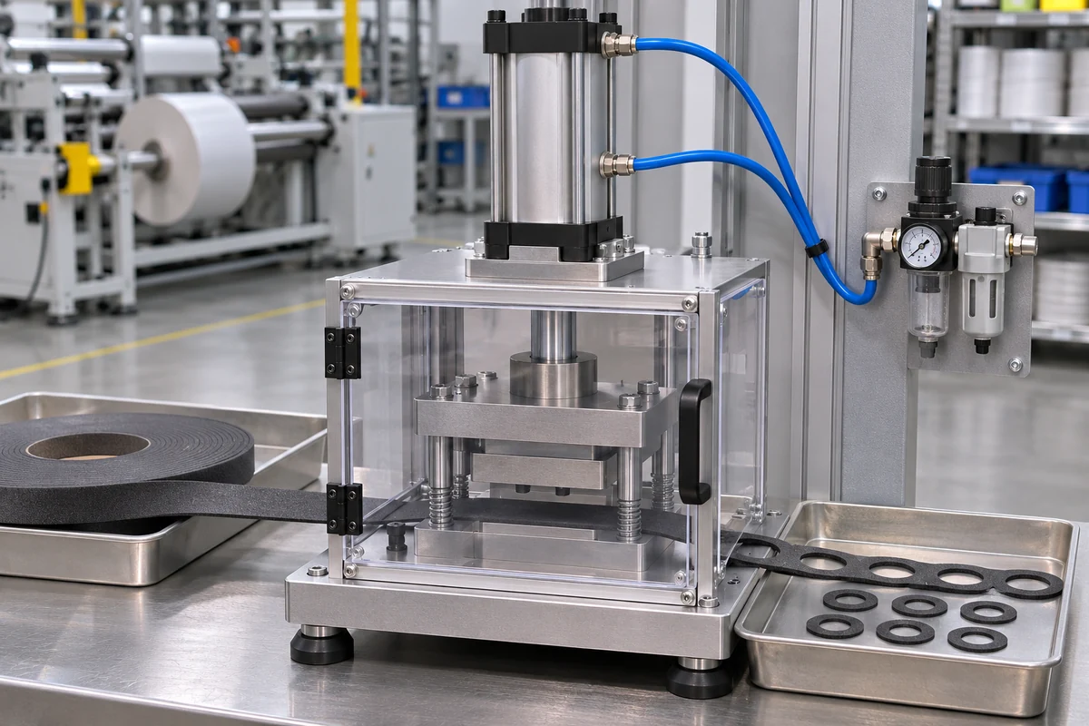
Concept illustration of a compact air-cylinder press for evaluating small gasket profiles.
For a simplified push-force estimate with negligible opposing pressure, multiply the cylinder pressure by the effective piston area. For a 100 mm bore on the full-piston side, the area is approximately 7,854 mm². At 6 bar, ideal thrust is about 4.71 kN. At 100 bar with the same effective area, ideal thrust is about 78.54 kN. These are illustrative calculations for two hypothetical, appropriately rated cylinders. Actual cylinder output and force at the tool depend on factors such as opposing pressure, friction, pressure drop and the machine’s mechanism and structural limits.[1][2] Use the supplier’s verified working-force specification for each quoted machine.
There is no universal foam thickness at which a buyer should switch to hydraulics. A thin frame with a long outside contour, a large opening and several holes can place more cutting edge in contact at once than a thicker small pad. More cavities can increase the combined cutting load further. Foam grade, density, compressibility, adhesive layers, liner construction and die geometry also matter. National Steel Rule describes how cutting-rule selection can change the edge profile of thicker foams.[3] Ask the supplier to test the hardest profile using the proposed tool and actual materials.
| Job variable | What to send the supplier | Why it matters |
|---|---|---|
| Gasket drawing | Outer perimeter, openings, holes, corner details and tolerances | Defines the cutting features and what the test must measure |
| Material stack | Foam grade, thickness range, adhesive and liner details | The die must handle the actual layers and their variation |
| Tool layout | Intended cavity count and orientation | Shows how much cutting edge engages and where the load sits |
| Usable work area | Stock width and maximum part dimensions | Confirms room for stock, guides and the die layout |
| Finished condition | Through-cut or kiss-cut, edge appearance and slug removal requirements | Defines how a good sample will be judged |
An uneven result between cavities is a reason to examine tool seating, platen support and load distribution. Increasing force alone can leave the underlying problem unresolved and may damage the tool or liner. Have the supplier identify the cause and demonstrate the corrected result under its approved test procedure.
Compare production speed and accuracy with the actual stock
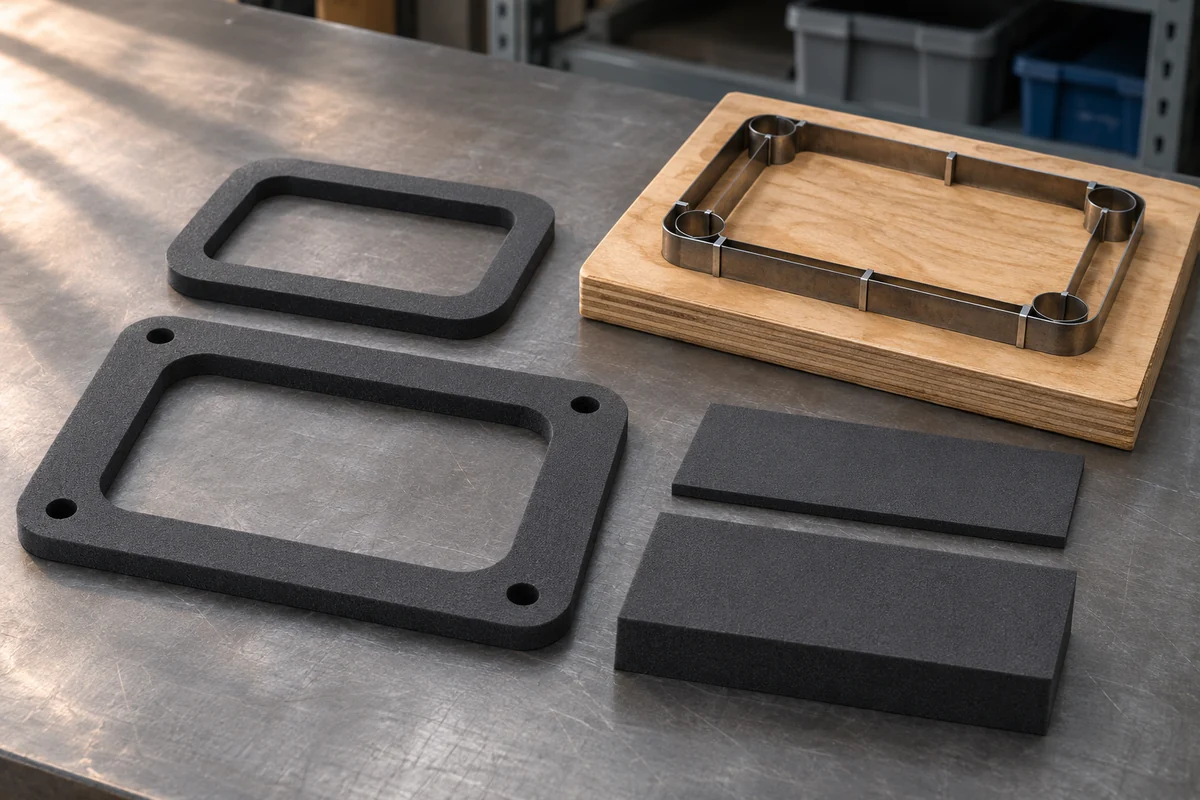
Concept illustration of foam stock, finished gaskets and tooling for a sample trial.
Start with the complete production cycle. Between two cutting strokes, the machine may need to advance and settle the web, punch a pattern, cut the perimeter, strip waste and collect the part. A compact pneumatic press can have a quick short stroke, while its feeder or part release may set the practical speed. Hydraulic presses can use different approach, cutting and return speeds, depending on the circuit and controls. Ask both suppliers to run the same material and report the full cycle with the collection method included.
Check dimensions independently of speed. For a punched hole, measure its position relative to the finished edge. For a frame, inspect the outside dimensions, inside opening and narrow bridges. When cutting adhesive-backed foam to a release liner, peel samples from different cavities and look for liner damage or incomplete separation. Use a measurement method agreed for compressible stock, with the time after cutting and handling conditions kept consistent. Record the first accepted pieces and take additional samples after the setup has run long enough for production conditions to stabilize.
Use accepted parts per scheduled hour as the comparison unit. For example, assume two cavities and 25 strokes per running minute. At 48 productive minutes per scheduled hour and a 96% acceptance rate, the result is 2,304 accepted parts. The calculation is illustrative. For a supplier trial, report actual accepted counts, stop time, observed rejects and what happened at roll changes. If the run is too short to capture planned interventions, label the measured result and model those interventions separately.
Compare utilities, maintenance and total operating cost
Purchasing teams should compare the delivered machine, utility work and process costs using the same production volume. On the pneumatic side, ask for air consumption at the specified pressure and target cycle rate, with units and reference conditions. Check the installed compressor’s capacity, demand from nearby machines and whether losses or restrictions can lower pressure at the equipment. The U.S. Department of Energy’s sourcebook discusses how leaks and pressure losses can affect compressed-air system performance.[4] Where possible, log pressure at the machine inlet while the trial runs.
For a hydraulic machine, request the power-unit specifications, fluid and filter requirements, and any cooling or temperature limits defined for sustained duty. Ask how the supplier will verify the machine during a representative run, especially when the application cycles continuously or operates in a warm shop. Confirm access for routine service and the availability of the required seals, hoses, filters and other wear items. A hydraulically driven press may still use compressed air for other functions, so ask for the requirements of the complete machine.
| Cost category | Ask the supplier to itemize |
|---|---|
| Machine and options | Cutting station, feed, safety equipment, waste handling, collection and electrical controls |
| Tooling | First production die, additional cavities, spare tooling and replacement lead times |
| Site utilities | Air supply and treatment, electrical installation, and cooling if specified |
| Ongoing production | Energy, servicing, scrap, changeover labor, stoppages and part handling |
| After-sales | Documentation, training, service scope and parts availability |
Request the machine’s guarding and energy-isolation documentation for the exact configuration. For U.S. installations, OSHA addresses guarding and hazardous energy control in separate standards.[5][6] A buyer evaluating an overseas installation should check the requirements that apply at the destination.
Choose a drive with a representative acceptance trial
Start with your highest-volume part and your most demanding part. These may be different drawings. For a small thin spacer, evaluate a pneumatic machine if the supplier can maintain the required working force and verify its air draw. For a wide frame or a die that engages many cavities at once, include a hydraulic option if the working area or force requirement makes it a better candidate. In either case, the meaningful result is the quality and volume achieved with the offered tooling and actual stock.
Provide a drawing revision, finished-part tolerances and production samples. State whether the material is supplied in sheets, rolls or precut strips. For rolls, include stock width, core size, outside diameter and loaded weight. Describe how the finished pieces should leave the line. Loose parts, parts carried on a liner and parts that must stay oriented for downstream loading may require different collection systems.
Agree on pass criteria before the trial. Ask the supplier to report sample measurements by cavity, the total quantity accepted, observed scrap problems and the actual tooling and utilities used. Request a running video long enough to show stable feed, the cut result and normal discharge. Ask whether changes between gasket sizes require a different die, guide setup or recipe. A buyer comparing several projects can use CUTOPIX’s Solar PV and New Energy equipment overview to review available process categories.
Frequently asked questions
Is a hydraulic press always more accurate?
Accuracy depends on how the machine feeds, supports and cuts the material. The frame and guides, tool condition, depth control and measurement method all affect the result. Ask for sample data from multiple cavities and at agreed points in the trial.
Does the air connection tell me which drive cuts the gasket?
The machine can use air for feeding, clamps or waste handling and a different system for the cutting stroke. Ask the supplier to identify the main cutting actuator, any secondary drive and each utility connection.
Can I choose a machine from foam thickness alone?
Send the full layer stack, usable stock width, die perimeter, cavity layout and output target. Thickness is one input. The tool and material trial establish whether the cut releases correctly and reaches the required rate.
Insights: How HAOXINHE evaluates EVA gasket applications
The CUTOPIX HX-200DK-B2 product page describes an automatic cold punching and cutting solution for thin EVA gaskets and other flexible materials. Request a written specification for the drive and utility requirements of the exact configuration quoted. HAOXINHE supports application review, material testing and remote technical support. For a new project, we can review the material construction and drawing with you and agree on what the sample test should demonstrate.
To request a machine recommendation, send your foam grade, thickness, usable width, feed format, gasket drawing, cavity or output target and installation utilities. Include a photo or sample of the liner when the job requires kiss-cutting. Contact CUTOPIX or email cherryhaoxinhesz@gmail.com.
References
- Parker Hannifin — Compact Hydraulic Cylinders, Theoretical Push and Pull Forces. Source
- SMC — Pneumatic Cylinder Sizing and Theoretical Force. Source
- National Steel Rule — Specialty Rules Solve Diecutting Problems. Source
- U.S. Department of Energy — Improving Compressed Air System Performance, A Sourcebook for Industry. Source
- U.S. Occupational Safety and Health Administration — 29 CFR 1910.212, General Requirements for All Machines. Source
- U.S. Occupational Safety and Health Administration — 29 CFR 1910.147, The Control of Hazardous Energy. Source