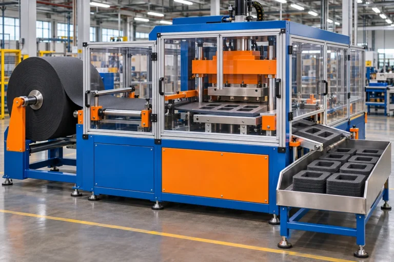
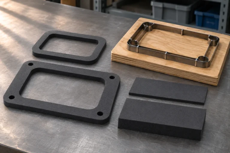
Why does a PV EVA gasket die cutting machine produce inaccurate cuts?
A PV EVA gasket die cutting machine can produce inaccurate cuts when the material slips or tracks sideways, the die is misaligned or worn, cutting depth varies across the tool, or the EVA compresses and changes shape as it relaxes. Measurement pressure can also make a soft gasket appear undersized. Start by identifying which dimension is wrong and whether the error repeats. A growing hole-to-hole pitch error points toward the feed. A clean opening in the wrong place suggests registration. An uncut corner that repeats in the same die position points toward local tooling or cutting depth. Compare consecutive parts under the same inspection conditions before changing settings.
This guide covers shaped EVA gasket stock, including foam and adhesive-backed constructions where specified. Confirm the material grade with your supplier. Photovoltaic module encapsulation uses EVA film as a laminate component with a different function and processing route.[1]
Classify the error before adjusting the machine
Start with the current drawing and an approved sample if one is available. Mark the feed direction on the collected samples and identify the drawing datum, such as the finished left edge or a locating hole. Record the actual measurements and their signs. A hole 0.6 mm too far toward the leading edge tells the technician more than a note saying the hole is off center.
| Defect pattern | First suspect | Check that narrows the cause |
|---|---|---|
| Identical hole offset on every part | Tool or station registration, or a wrong datum | Compare the hole center from two drawing datums and verify the tooling revision |
| Pitch error grows over successive indexes | Feed scale error or repeatable slip | Measure the actual advance across multiple indexes |
| Side margin widens and narrows | Lateral web movement or skew | Track the stock edge against a fixed reference through several cycles |
| One cavity makes parts consistently too small | Cavity geometry, rule condition or local compression | Identify parts by cavity and compare the same feature across cavities |
| A tab stays attached at exactly one corner | Local penetration, a damaged cutting edge or a worn cutting surface | Map the defect to the tool and cutting surface coordinates |
| Measurements change between inspectors | Measurement setup or pressure on the foam | Have both inspectors repeat the same measurement on the same parts |
A machine that makes every gasket 0.5 mm too short with little variation calls for a different investigation from a machine that alternates between short and long parts. In the first case, verify the drawing, recipe, tool and any fixed offset. In the second, look for movement, inconsistent stock or an unstable inspection method. A single average can hide both a repeating pattern and a bad cavity. Keep the readings in production order and mark where roll changes, restarts and speed changes occurred.
Measure the geometry and the position separately. For a rectangular gasket with a punched opening, record the outer width and length, the opening width and length, and the two opposing margins. An opening of the correct size with a thin margin on one side and a thick margin on the other has moved relative to the perimeter. If the margins remain balanced and both are too narrow, check the opening size and outer dimensions before changing the station timing.
Check feed length, web tracking and punch-to-cut registration
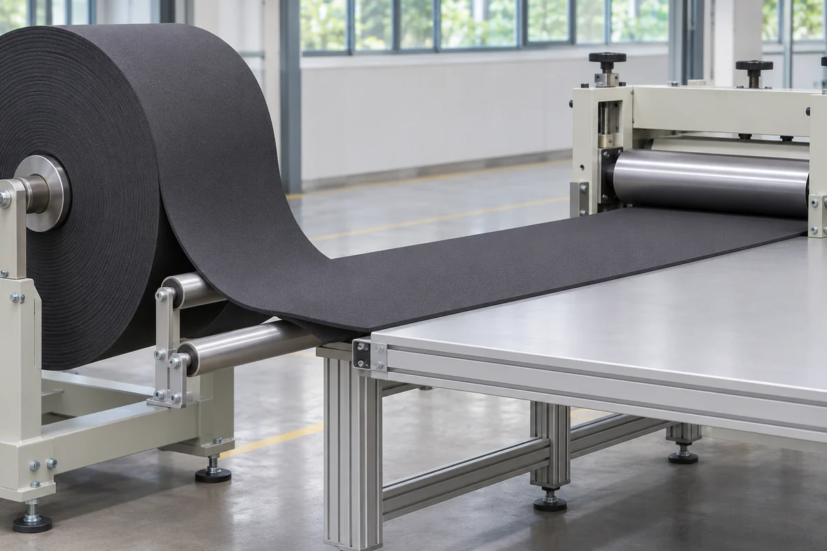
On a roll-fed machine the controller can issue the correct feed command while the stock travels a different distance. Contaminated or worn rollers can lose grip. Unwind drag can change as the roll runs down. A soft web can also stretch under tension and recover after cutting. Web-handling guidance from Maxcess identifies roller alignment and tension variation among causes of web defects such as wrinkling.[2] Check whether the defect follows feed direction, moves across the width, or appears at a particular point in the run.
Measure actual stock travel through a known number of indexes using the machine supplier’s approved verification procedure. For example, ten commanded advances of 80.0 mm give a nominal travel of 800.0 mm. If repeated checks under the same conditions show 798.0 mm, the average shortfall is 0.2 mm per index. This example identifies a repeatable shortfall to investigate. Check for physical slip before changing the feed scale. If the result changes between runs, record roll size, speed and material lot as you look for the condition that changes the advance.
For lateral errors, record the stock edge position near the entry to the cutting station and compare it with the finished side margins. If the edge wanders and the margins follow it, have the feed path, roll mounting and guides checked. A stable edge with a skewed finished part puts more attention on tool alignment, stock squareness or movement during the cut. For sheet-fed equipment, run the same comparison using the sheet stops and locating surfaces as references.
Punching and final cutoff can occur at different positions in an integrated machine. If individual holes and outlines are clean but their relationship is wrong, confirm the station offset and whether the error begins after a recipe change or restart. When a system registers to printed marks, compare the detected and physical mark positions under production conditions. For jobs referenced to the material edge, check edge position directly.
Inspect the die, cutting pressure and material together
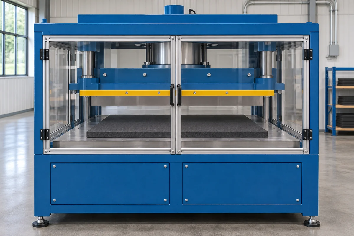
A local cut defect can look like a geometry error. On a frame gasket, a small section left attached to the waste can stretch during separation and leave a torn edge or a distorted corner. Determine whether the stock was cut cleanly through before checking the outer profile. In a kiss-cut application, also inspect the liner in accordance with the drawing or work instruction. A deep cut into the release liner presents a different defect from a bridge left in the foam.
| Observation | What to check | Evidence to retain |
|---|---|---|
| Same corner or hole is incomplete each cycle | Local rule or punch condition, die seating and cutting surface | Close-up, cavity ID and location on a tool sketch |
| Several cavities fail along one side | Local penetration and platen or cutting surface condition | Map of failures across the tool width |
| Defect appears only on thicker or laminated stock | Actual thickness, backing construction and validated setup | Material lot, sample and thickness readings |
| Frames distort during stripping | Waste separation and support around narrow sections | Samples before and after stripping, collected through the approved procedure |
On a flatbed press, force distribution and cutting depth can vary across the working area. BOBST describes platen compensation for pressure-related deformation on certain die cutters, illustrating why a localized defect deserves a localized inspection.[3] If one side has attached fibers and the opposite side leaves excessive impressions, document both patterns. Have trained personnel inspect the die seating, cutting surface and relevant press setup using the manufacturer’s procedure. A blanket increase in force can deepen an already aggressive cut elsewhere.
Compare the geometry of the installed tool with the current drawing. On repeat jobs, identify the exact cavity, insert or punch involved. If the defect appeared immediately after a tooling change, check the tool ID and setup record. If the same area gradually deteriorated over several batches, check for a worn edge, damaged insert or localized wear on the cutting surface.
Check the material label and measure actual thickness at several representative locations using the agreed method. Two nominally identical EVA stocks can have different foam density, backing or adhesive construction. If the parts shift in size after they are released or after the liner is removed, compare them in the same defined condition. Keep samples from the suspect lot and from a lot that previously ran well. Use the same drawing, measuring method and validated recipe when comparing them. For servicing tasks exposing workers to hazardous energy, follow the applicable energy-control procedure. In US workplaces, OSHA’s lockout/tagout standard describes the controls for covered servicing and maintenance.[4]
Verify the measurement and reproduce the fault at production speed
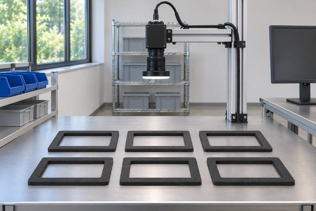
A usable inspection method tells people how to support the part, which datum to use and when to measure after cutting. Specify whether dimension checks are made with the liner on, with the liner removed or in an assembled condition if that is what the drawing requires. Soft foam can compress between contact jaws. A part can also bow or curl on an uneven surface. Use a suitable low-force or validated optical method where appropriate. An optical system still needs checks for scale, edge contrast and repeatable part placement, especially when a dark gasket has a rough or beveled edge.
Give two inspectors the same labeled samples and have them measure the same features independently with the agreed setup. Keep their repeated readings in order. If readings from the same sample vary by an appreciable share of the applicable tolerance, investigate the measurement method before deciding how much the cutting process varies. NIST’s gauge R&R guidance describes how to assess repeatability and reproducibility in production measurement.[5]
| Trial | What to hold constant | What to record |
|---|---|---|
| Repeat the measurement | Same part, datum and material condition | Differences within and between inspectors |
| Run at a controlled trial speed | Drawing, tool, lot and inspection method | Consecutive readings, cavity and feed direction |
| Repeat at the target production speed | Same tool, lot and inspection method | Changes in pitch, side margin, edge quality and reject count |
| Check after a restart or roll change | Approved recipe and inspection method | First-off and later readings plus any change in defect pattern |
Change one approved setting at a time. If the trial passes at reduced speed and fails at normal speed, compare actual advance, lateral position and registration before making a permanent speed adjustment. Look for whether the failure begins during startup, when the roll diameter changes or after the press has been running steadily. If the same cavity fails at both speeds, check its local tooling and support. Preserve labeled good and bad parts alongside the recorded settings so the next trial has a meaningful baseline.
Define a finished-part acceptance test before buying or changing equipment
Ask the supplier to run the production material with the target thickness, width, backing and roll or sheet format. Provide the drawing and identify which dimensions govern assembly. A gasket may need the inner opening to align with a mounting feature, while its outside edge has a different tolerance. Specify the hole-to-edge position, minimum wall width and how edge tearing or attached waste will be judged. If adhesive-backed stock must stay on its release liner, define what an acceptable liner looks like after cutting.
Agree on a run length, sample frequency and measurement method suited to the job. Include enough consecutive pieces to detect short-term drift. Identify samples by cavity where the tool makes multiple parts in one stroke. For continuous production, consider measurements at startup, during steady running and after a representative restart or roll change. Request actual readings, labeled samples and a video that shows the stock entering the machine and the finished cut. Use the drawing limits as the acceptance criteria. A display resolution or a controller increment describes the setting available to the operator. Finished-part results also depend on the tooling, material, handling and inspection system.
When comparing quotations, identify which features the quoted machine uses to control the stock and register successive operations. A roll-to-sheet machine can prepare rectangular blanks when that is a separate stage in the process. A shaped opening or punched hole pattern calls for tooling and a positioning method matched to the drawing. See the related CUTOPIX roll-to-sheet cutting solutions.
Frequently asked questions
Why does the gasket length look correct but the hole position is wrong?
The cutoff can produce the right length while the punch is displaced relative to the part datum. Measure each hole center relative to the intended finished edge, then compare successive parts. A fixed offset points toward registration or tooling. A changing offset calls for a check of actual feed and stock movement between operations.
Can slowing the machine fix inaccurate EVA die cuts?
A lower trial speed can reveal a speed-dependent fault. If accuracy improves, compare stock advance, web stability and station timing at both speeds. For a recurring defect at the same cavity, inspect the tool and cutting surface even if slower operation makes the defect less visible.
Why did accuracy change after switching EVA rolls?
The new roll can differ in actual thickness, backing, curl or how it feeds under the same setup. Check the lot and roll condition and run a controlled comparison with previously accepted stock. Use the same inspection method and retain samples from both runs.
Insights from HAOXINHE on PV EVA gasket applications
We review EVA samples and drawings to help choose a cutting and punching sequence for the finished geometry. For an existing production issue, send a photo of the complete part, a labeled close-up of the defect and a short table of consecutive measurements. Include the machine model, tool or cavity ID, feed direction, material lot and whether the readings change at normal production speed. Those details help determine which setup or tooling feature to examine and what to reproduce in a trial.
For a new project, see the CUTOPIX HX-200DK-B2 Solar PV EVA Gasket Punching & Cutting Machine and the solar PV and new energy applications guide. We can review your sample, discuss the available configuration, and arrange application-specific cutting tests and video documentation. Confirm the resulting dimensions and edge quality on representative samples before accepting a machine for a specific gasket.
Conclusion
Match the investigation to the defect pattern. For errors that accumulate along the roll, measure real stock advance. For misplaced holes, inspect their relationship to the finished datum. For recurring bridges or tears, map the defect to the cavity and check cutting depth and tooling. Verify the measurement method before accepting the final result. Send the EVA grade, backing, thickness, stock width, roll or sheet format, finished dimensions, drawing tolerances and target output to CUTOPIX or email cherryhaoxinhesz@gmail.com to discuss a sample test.