How Does a PV EVA Gasket Die Cutting Machine Work for Solar Panel Sealing Production?
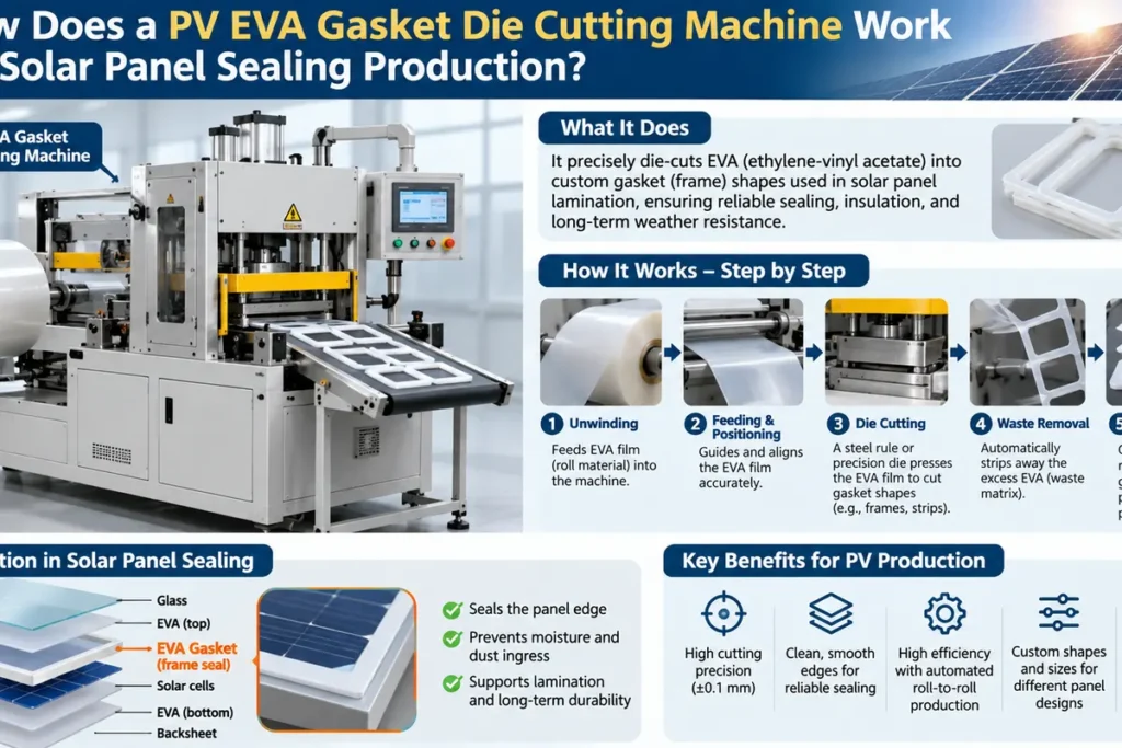
A PV EVA gasket die cutting machine converts rolls of thin, flexible EVA gasket material into repeatable shapes by feeding the material to a registered position, pressing a shaped die through it, cutting the finished part to size, and collecting the output. For suitable designs, punching and cutting can take place in one automated sequence. The goal is consistent dimensions, clean edges, predictable output, and reduced manual handling for manufacturers supplying sealing or insulating components to photovoltaic (PV) production lines.
Important distinction: An EVA gasket is a shaped component used where a PV assembly design calls for cushioning, spacing, insulation, or sealing. It is not the same product as the large-area EVA encapsulation film laminated around solar cells. Nor should an EVA gasket be assumed to replace a qualified module edge sealant. The actual function and suitability of any gasket must be verified against the module manufacturer’s design and reliability requirements.
What Does a PV EVA Gasket Die Cutting Machine Actually Do?
A die cutting machine is a material-converting system, not a solar-cell laminator. Its task is to make accurately shaped parts from supplied EVA gasket stock. A typical job begins with a roll or strip and ends with finished pieces that can be transferred to a separate assembly operation. Depending on the drawing, these pieces may have straight edges, rounded corners, slots, internal holes, or other die-cut profiles.
The machine must solve several problems at once. Flexible EVA can stretch as it is pulled, so the feeding system must advance material consistently. Thin stock may curl or stick to tools. A poorly matched die can leave incomplete cuts, ragged edges, or unwanted deformation. And even if every individual part looks acceptable, small feed errors can accumulate during continuous operation. The machine therefore combines controlled material transport, registration, a suitable cutting tool, and a repeatable operating sequence.
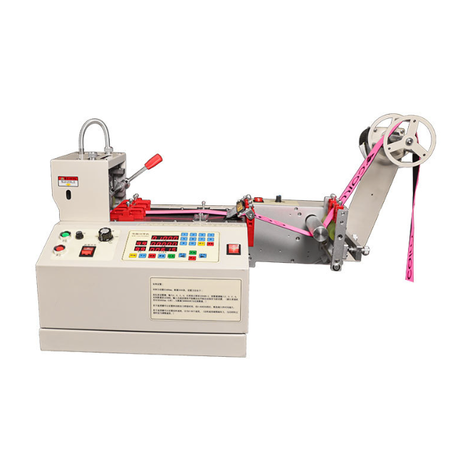
For the CUTOPIX HX-200DK-B2 solar PV EVA gasket punching and cutting machine, the published application is thin EVA gasket and other flexible new-energy materials. The listed configuration uses cold cutting and combines automatic feeding, positioning, punching, and cutting. Its stated material-width range is 1–200 mm, with a listed material-thickness range of 0.01–5 mm; these are catalog limits, not a promise that every EVA formulation or geometry will work across the full range. The product page also describes approximately 500–800 pieces per minute for suitable jobs, depending on part size, material, and die design. Real output must be confirmed by testing the buyer’s exact parts.
| Operation | What the machine controls | Why it matters |
|---|---|---|
| Unwinding and feeding | Roll handling, strip path, advance distance | Reduces stretching and inconsistent pitch |
| Positioning | Material alignment and registered feed | Keeps holes and outside edges in the right places |
| Die punching | Tool shape, stroke, and penetration | Produces holes, slots, and custom profiles |
| Final cutting | Separation of the finished part | Delivers the required length and outline |
| Collection and inspection | Part removal and quality checks | Helps detect defects before assembly |
A useful purchase question is therefore not simply “How fast is the machine?” It is “Can this machine make our drawing, from our actual material, at our required acceptable-part rate?”
EVA Gasket Materials and Their Sealing Applications
EVA stands for ethylene-vinyl acetate, a family of polymers with properties that vary by formulation, vinyl-acetate content, fillers, foam structure, and additives. Some gasket stock is dense and flexible; other material is foamed, adhesive-backed, or supplied on a release liner. These variations affect the force needed to cut, how the strip behaves under tension, and how a finished part retains its dimensions.
A PV manufacturer may use a shaped polymer component as a spacer, cushioning pad, insulating gasket, or part of a specifically engineered sealing assembly. However, a gasket’s presence does not by itself establish a waterproof or durable solar module. Moisture resistance depends on the complete module architecture, adhesion, interfaces, edge sealing, and validation testing. NREL’s overview of PV encapsulation emphasizes the importance of packaging materials and moisture-related reliability issues.[1]
Before ordering a cutting machine, obtain the material’s technical data sheet and a representative production sample. Ask whether the stock is solid or foamed, whether it contains adhesive, whether it is laminated to another layer, and whether dimensions are specified before or after relaxation. If a buyer only says “EVA film,” clarify whether the job involves narrow gasket parts or full-width solar encapsulant sheets. These are different converting applications, often requiring different equipment.
| Material or part feature | Possible cutting challenge | What to verify |
|---|---|---|
| Thin flexible EVA strip | Stretch during feeding | Feed repeatability and part length |
| Foamed EVA | Compression and edge distortion | Cut edge after recovery |
| Adhesive-backed EVA | Tool sticking or liner damage | Tool release and liner requirements |
| Multi-layer laminate | Uneven penetration | Complete cut through intended layers |
| Small holes or narrow bridges | Scrap retention or tearing | Hole quality and minimum feature size |
| Tight-tolerance profile | Material relaxation after cutting | Measurements after an agreed wait time |
The right cutting method depends on both the material and the intended finished part. Through-cutting separates the part completely. In adhesive-backed converting, a specially configured kiss-cutting process can cut the upper material while preserving a carrier liner, but this capability must be confirmed for the exact machine and tooling; it should not be assumed from a general die-cutting description.
How the Automatic Die Cutting Process Works Step by Step
1. Load the EVA roll and guide the strip
The operator installs a roll on a compatible unwind system and threads the strip along the defined path. Guides should keep the material centered without squeezing or deforming it. Roll diameter, core size, roll mass, and unwind resistance all matter. A machine may have enough cutting width yet still need a different unwind arrangement for a heavy roll.
2. Enter the cutting recipe
The operator sets the applicable feed distance, quantity, and machine operating parameters. The physical die determines the shape of holes or profiles; a control-panel setting alone cannot create arbitrary new tool geometry on a fixed-die machine. When changing to a new gasket drawing, the operator may need a different die as well as a revised feed recipe.
3. Advance and register the material
The feed mechanism advances the EVA by the required pitch. Guides and sensors, where fitted, help maintain alignment. Pitch is not always equal to finished-part length: it can include clearance between neighboring profiles and the layout needed for punching. Incorrect pitch can waste stock or make adjacent cuts overlap.
4. Punch the custom shape
A matched cutting die presses into the EVA. Depending on the tool, it may create an outer profile, internal opening, slot, or multiple features in one stroke. Cutting pressure and die clearance must suit the material. The die must also be maintained; a dull edge may compress or tear rather than cut cleanly.
5. Separate, remove scrap, and collect
The finished gasket is separated according to the tooling sequence. Small hole slugs and surrounding scrap may need a removal method tailored to the part. Collection can be manual or automated depending on the actual configuration. Operators inspect initial pieces before running at production speed, then continue checking dimensions and edge quality during the run.
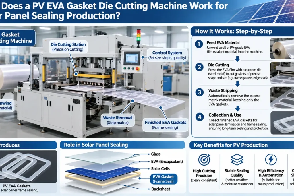
The sequence above describes the general operating principle, not a claim that every listed accessory, waste-removal system, or automatic stacker is standard equipment. Buyers should request a machine-running video that shows the full path from incoming roll to finished output, including the scrap stream.
How to Choose the Right Machine and Die Configuration
Machine selection starts with the gasket drawing. The drawing should show the outer shape, total length and width, hole sizes, center-to-center distances, corner radii, and allowable tolerances. A sample part is useful, but a sample without dimensional notes can leave important questions unanswered. If the part has an adhesive liner, show the layer stack and specify which layers must be cut.
Next, compare the drawing with the machine’s working envelope and the intended die layout. A 200 mm maximum material width does not mean every 200 mm-wide gasket can be punched in every orientation. Clearance, material margins, tool mounting, and feed direction may reduce the usable layout. Multiple-up dies can produce several pieces per stroke, but they also change cutting force, waste pattern, tooling cost, and scrap handling.
The CUTOPIX new-energy material cutting category includes other film and insulation processing equipment. Those products should be considered only if their material path and cutting method match the job. Buyers processing large-area encapsulation film should not automatically select a narrow-strip gasket die cutter.
| Buyer requirement | Information to send | Selection consequence |
|---|---|---|
| Material | Grade, thickness, density, adhesive or liner | Feed and cutting method |
| Dimensions | Dimensioned drawing and tolerance | Die size and feasibility |
| Hole pattern | Diameters, locations, minimum spacing | Punch design and slug removal |
| Roll specification | Width, outer diameter, core, weight | Unwind and feeding arrangement |
| Production goal | Good parts per hour and shift pattern | Required cycle time and automation |
| Downstream process | Loose parts, stacks, or liner-supported parts | Collection or transfer method |
| Plant conditions | Voltage, air supply, safety requirements | Electrical and machine configuration |
A reliable quotation should identify the base machine, included die, spare tools, optional modules, electrical requirements, commissioning support, and acceptance test. It should also explain whether a future part design requires changing the die. “Adjustable size” can mean changing feed length; it does not necessarily mean tool-free production of any new shape.
Cutting Accuracy, Speed, and Finished Gasket Quality
For sealing and insulating components, accuracy is more than a single tolerance number. A part can have the correct overall length but still fail because a hole is off-center, a corner is torn, or a thin bridge has stretched. Inspection should cover both geometry and appearance. Measurements should use a defined method and agreed sampling plan so buyer and supplier compare the same thing.
Feed repeatability, die condition, material thickness variation, and tension all influence finished dimensions. Some flexible materials also change slightly after they leave the cutting zone. For that reason, evaluate samples after a consistent resting period, especially if the final application has tight assembly clearances. Do not assume a catalog figure for a different material is valid for EVA.
Production speed must be interpreted carefully. A high stroke rate is useful only when the machine delivers acceptable finished parts without frequent stops. The published HX-200DK-B2 output figure is application-dependent. A larger die, complex hole pattern, difficult scrap, or delicate material may require a slower cycle. In production planning, calculate good parts per hour, not just theoretical strokes per minute.
For example, if a hypothetical process produces 120 parts per minute for 50 minutes of productive running within an hour, its gross output is 6,000 pieces. If 2% fail inspection, acceptable output is 5,880 pieces. This is an illustrative calculation, not a tested HX-200DK-B2 production result. The calculation demonstrates why downtime and reject rate should be included when comparing equipment.
Common Die Cutting Problems and Practical Solutions
A recurring problem with thin EVA is wandering material. If the strip drifts sideways, punched holes move relative to the outside edges. Start by checking roll alignment, guides, feed rollers, and tension. Increasing pressure indiscriminately may create a new problem by stretching or marking the material.
Incomplete cuts often indicate a mismatch between the die, material stack, and cutting setup. Check tool sharpness, the backing surface, and whether the actual material thickness matches the sample used to design the die. If hole slugs remain attached, investigate the punch geometry and removal method rather than simply raising speed.
A third problem is adhesive buildup. For adhesive-backed stock, residue can accumulate on the die and interfere with consistent cutting. The correct remedy may include tool cleaning, a suitable release treatment, or a different cutting configuration. Any chemical or coating used must be compatible with the product and downstream application.
| Observed defect | Likely causes to investigate | First corrective action |
|---|---|---|
| Hole location drifts | Feed slip or sideways tracking | Inspect guides and feed registration |
| Ragged edges | Dull die or poor cutting setup | Inspect and service tooling |
| EVA stretches | Excessive tension or roller pressure | Reduce stress in material path |
| Slugs remain attached | Incomplete punch or poor scrap extraction | Review punch and scrap handling |
| Part sticks to die | Adhesive or material tack | Check release and cleaning procedure |
| Output varies over a shift | Roll changes, tool wear, inconsistent setup | Record conditions and inspect samples |
A sensible troubleshooting routine changes one variable at a time, records before-and-after results, and retains sample parts. That makes it easier to distinguish material issues from machine setup problems.
Production Cost, Maintenance, and Waste Reduction
The purchase price of a die cutter is only one component of production cost. Buyers should also consider tooling, setup time, spare parts, rejected material, operator labor, electricity, and maintenance. A lower-priced machine may cost more to operate if it needs frequent intervention or cannot hold the required geometry. Conversely, an expensive automated configuration is not automatically the best choice for low-volume work with many different shapes.
Material utilization depends strongly on part nesting, strip width, spacing, and scrap design. A die layout with tighter spacing may reduce waste, but it must preserve enough material between features for reliable feeding and cutting. The CUTOPIX guide to reducing EVA gasket die-cutting waste explores related decisions in more detail.
Maintenance should focus on cutting tools, feed rollers, guides, sensors, fasteners, and any scrap-removal components. Establish inspection intervals from actual production conditions rather than an unsupported universal schedule. Keep tooling clean and record the material, settings, die identification, and measured results for each approved product. Before maintenance or clearing jams, isolate hazardous energy according to the machine instructions and the facility’s safety procedures; never bypass guarding to save cycle time.
For a new installation, the most useful acceptance test uses the buyer’s actual material and drawing. Agree in advance on sample count, measurement points, permissible defects, continuous-run duration, and what constitutes a pass. A video is helpful, but it should complement, not replace, documented measurements.
)
Frequently Asked Questions About PV EVA Gasket Die Cutting
Is an EVA gasket die cutter the same as an EVA encapsulation film cutter?
No. A gasket die cutter makes shaped components, often from narrow rolls or strips. An encapsulation film cutter typically prepares larger sheets for module layup and lamination. The materials may share an EVA chemistry, but their geometry and production workflows differ.
Can punching and cutting be completed automatically?
Yes, suitable machines can combine registered feeding, die punching, and cutting in a continuous sequence. The exact order, part separation, and collection method depend on the selected tooling and configuration.
Can one machine make different gasket shapes?
Often yes, if the machine supports interchangeable tooling and the new shapes fit its working range. Changing a programmed feed length is not the same as changing a die-cut outline. Confirm die-change requirements before purchasing.
Can the machine cut EVA foam or adhesive-backed EVA?
Possibly, but not without verification. Foam compression, adhesive tack, backing liners, and layer thickness all affect the process. Submit representative samples and clarify whether full cutting or liner-preserving kiss cutting is required.
Does a cleanly cut EVA gasket guarantee a waterproof solar panel?
No. Sealing performance depends on the qualified gasket material, joint design, assembly conditions, and complete PV module construction. Cutting quality is important, but module reliability must be validated separately.
What should I ask the supplier to demonstrate?
Ask for a continuous video of roll feeding, die action, finished parts, and scrap handling. Request measured samples from your own material, plus the agreed test conditions and list of included machine options.
Insights: How HAOXINHE Supports Solar PV EVA Gasket Cutting
At HAOXINHE / CUTOPIX, we approach a custom gasket-cutting inquiry by first reviewing the actual material and finished-part requirements. For thin solar PV EVA gasket applications, our HX-200DK-B2 punching and cutting machine is a relevant starting point, but we do not assume that one standard setup is suitable for every EVA formulation or gasket drawing.
We can review dimensions, hole patterns, material thickness, roll format, and the requested production workflow. Where the project requires a custom die or feeding configuration, these details guide the engineering discussion. We also support sample-based testing and can provide machine-running videos before shipment for buyer review. The purpose is to establish whether the finished part meets the agreed drawing and quality expectations, rather than relying only on general catalog descriptions.
International buyers can also discuss electrical requirements, optional handling modules, packing, and remote technical support. If you are sourcing equipment for a PV supplier or a new-energy component factory, send us the material grade, thickness, roll width, finished gasket drawing, hole pattern, target good-parts-per-hour rate, and available sample photos. We can then review the cutting method and suitable configuration.
Conclusion
A PV EVA gasket die cutting machine works by controlling material feed, registering the strip, punching the required profile, separating finished parts, and managing collection and scrap. Its real value lies in repeatable parts that meet a buyer’s drawing—not in a headline speed alone. Distinguish gasket converting from encapsulation-film cutting, verify material compatibility, and request a sample test before confirming the machine and tooling.
For a configuration review, contact CUTOPIX or email cherryhaoxinhesz@gmail.com with your EVA material and drawing.
References
- National Renewable Energy Laboratory — PV Module Encapsulation: Materials, Process, and Reliability. Read the technical paper.
- U.S. Department of Energy technical report — Post-Lamination Manufacturing Process Automation for Photovoltaic Modules. Read the report.